东西辣么贵,货期辣么慢,加班辣么多,悲伤辣么大。
前言
由于某不知名飞控仅支持部分国内不常见的激光雷达,而采购过程又贵又慢,因此产生了本篇记录,尝试利用更易获取的平价激光雷达配合 Arduino 来代替 LIDAR-Lite v3。
替换设备与目标设备信息
Lidar Lite v3工作模式
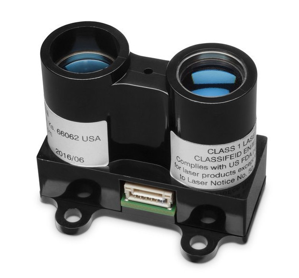
When space and weight requirements are tight, the LIDAR-Lite v3 soars. It’s the ideal compact, high-performance optical distant measurement sensor solution for drone, robot or unmanned vehicle applications. Using a single chip signal processing solution along with minimal hardware, this highly configurable sensor can be used as the basic building block for applications where small size, light weight, low power consumption and high performance are important factors.
Featuring all of the core features of the popular LIDAR-Lite v2, this easy-to-use 40 meter laser-based sensor uses about 130 milliamps during an acquisition. It is user-configurable so you can adjust between accuracy, operating range and measurement time. It’s reliable, powerful ranging and it’s the proximity sensor you need.
——摘自佳明官网
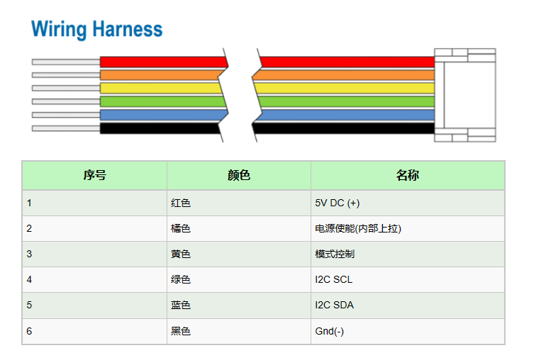
设备默认以I2C形式输出高度数据,同时也提供了一个模式控制线用于切换为PWM输出。
北醒TF系列雷达工作模式
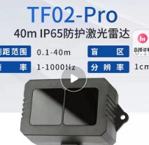
查看对应型号激光雷达的官方文档,这里以TF02 Pro为例:
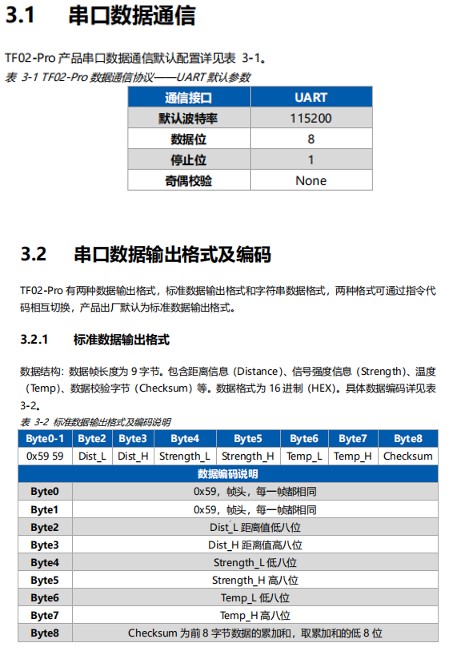
使用串口模块连接激光高度计核对通信设置以及数据位,并根据数据长度创建结构体并输出。
实现方式
使用Arduino等单片机通过串口获取激光高度计数据,再通过PWM引脚输出相应比例脉宽来模拟目标替换设备。
代码部分
Arduino nano 与TF02 Pro组合的代码(TF02 Pro在2米高度下以该种形式输出脉宽对应的距离约为2.072米)
  typedef struct {
    int distance;
    int strength;
    int temp;
    boolean receiveComplete;
  } TF;
  TF Lidar = {0, 0, 0, false};

  void getLidarData(TF* lidar) {
    static char i = 0; // 记录接收数据索引
    char j = 0; // 循环计数
    int checksum = 0; // 校验和
    static int rx[9];
    if (Serial.available()) {
      rx[i] = Serial.read();
      if (rx[0] != 0x59) { // 检查是否为0x59
        i = 0;
      }
      else if (i == 1 && rx[1] != 0x59) {
        i = 0;
      }
      else if (i == 8) {
        for (j = 0; j < 8; j++) { // 计算数据校验和
          checksum += rx[j];
        }
        if (rx[8] == (checksum % 256)) { // 检查数据校验和
          lidar->distance = rx[2] + rx[3] * 256; // 距离值存储
          lidar->strength = rx[4] + rx[5] * 256; // 强度值存储
          lidar->temp = (rx[6] + rx[7] * 256) / 8 - 256; // 温度值存储
          lidar->receiveComplete = true;
        }
        i = 0;
      }
      else {
        i++;
      }
    }
  }

  void setup() {
    Serial.begin(115200);
    pinMode(9, OUTPUT); // 9设置为输出
  }

  void loop() {
    getLidarData(&Lidar);
    if (Lidar.receiveComplete) {
      Lidar.receiveComplete = false;
      digitalWrite(9,HIGH);
      delayMicroseconds(Lidar.distance*10); // 延迟为距离值乘以10微秒
      digitalWrite(9,LOW);
      delayMicroseconds(Lidar.distance*10);
      Serial.print(Lidar.distance); // 打印距离值
      Serial.println();
    }
}烧录代码后,将雷达与Arduino连接,并通过串口查看输出距离,当确定距离值与实际情况基本一致后,使用示波器探针连接输出脚检查脉宽。
硬件连接
先看看官方的连接示意图
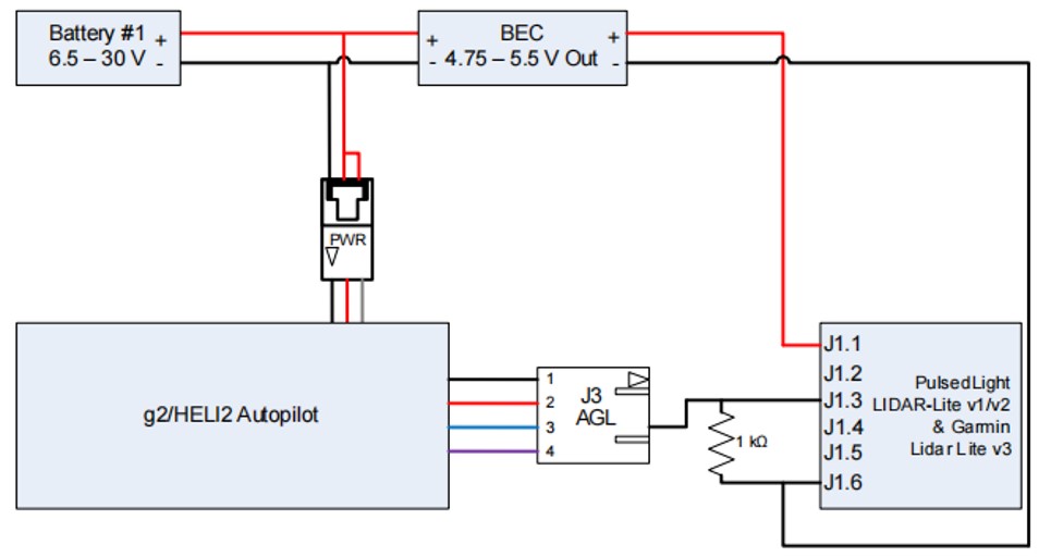
高度数据通过AGL接插件蓝色线传输。直接将其与arduino的D9连接。激光高度计的供电部分由arduino提供,arduino的供电来自舵机板的5V供电。 作为MCU以及单片机的常见通信电平标准。LVTTL在无数据通信时会维持在3.3V左右的电压范围。
上位机设置
打开VRS的传感器选项卡,将AGL部分如下图设置
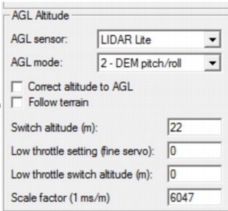
检查飞控字段,此时可以正常显示高度数据。
